Console Disassembly
The 555 follows the standard Wurlitzer spinet/console construction of the era: every playing surface and control panel is hinged at the rear and lifts or pivots forward for service access. The console is a stack of hinged layers — top lid, cheek blocks, stoprail, upper manual, lower manual — each of which must be removed or pivoted in order from the top down.
No tools are required for normal disassembly. The entire console opens with latches, clips, and gravity.
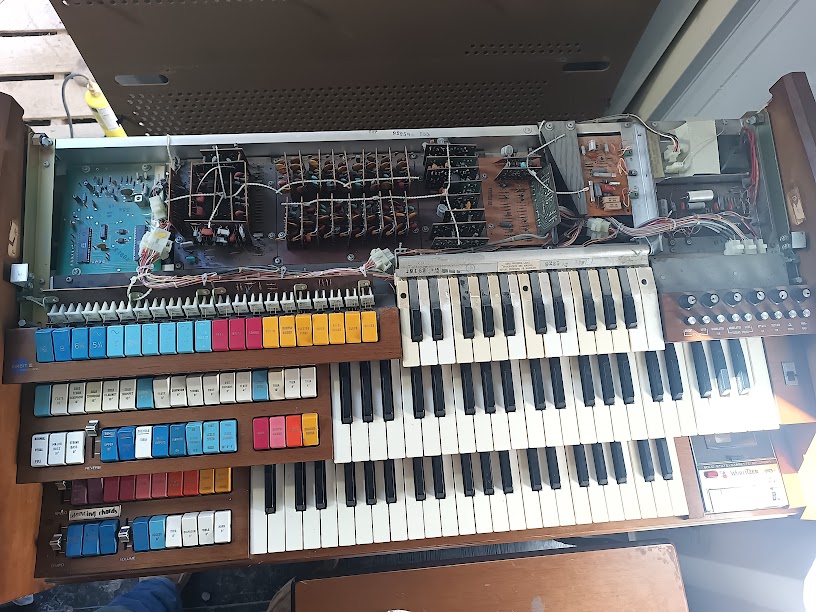 Console with top cover removed and stoprail pivoted forward. The upper manual’s key contacts, circuit boards, and wiring harnesses are all visible. The colorful tab stops (left), Orbit III mini-keys (lower left), and cassette deck (lower right) are in their normal playing positions. Photo: Ryan Malloy.
The Layered Architecture
Section titled “The Layered Architecture”The 555’s console is built like a series of nested lids. From top to bottom:
- Top lid — the flat surface above the music rack
- Cheek blocks — decorative side panels flanking the keyboards
- Stoprail — the angled panel holding all the tab stops
- Upper manual (Swell) — 44 keys, hinged at the rear
- Lower manual (Great) — 44 keys, hinged at the rear
- Orbit III panel — the mini-key synthesizer, below the lower manual
Each layer must come off or pivot before the one below it is accessible. The keyboards don’t slide out — they tilt up and forward on their rear hinges, exposing the bus bars and contact wiring underneath.
Disassembly Procedure
Section titled “Disassembly Procedure”-
Remove the top lid
The top lid sits in a channel and is retained by Phillips screws at the cheek block corners. The critical detail: slide the lid forward first, then lift. Trying to lift straight up will bind it against the rear hinge or retainer strip. Once slid forward an inch or two, the lid lifts free.
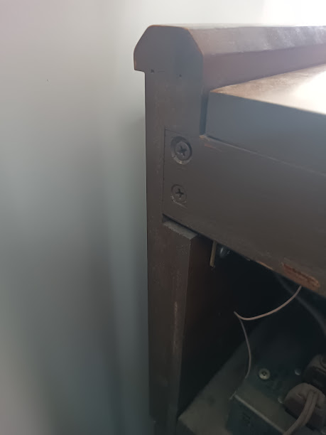 Phillips screws at the cheek block corners retain the top lid. Photo: Ryan Malloy.
With the top lid removed, the LSI board (divider-keyers and TOS) is immediately accessible at the top left — no further disassembly needed to reach those ICs. See What’s Underneath for details.
-
Remove the cheek blocks
The decorative wood panels on each side of the keyboards are held by screws at the top. With the top lid removed, the cheek block retainers are accessible. Lift each cheek block straight up and off its mounting pins. Set them aside — they’re cosmetic but easy to scratch.
Keep the hardware organized — a muffin tin works well for separating the different screw types.
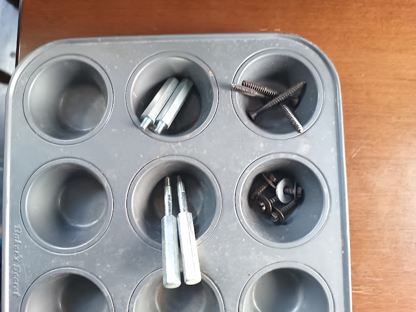 Hex standoffs (cheek blocks) and Phillips screws (top lid) organized during disassembly. Photo: Ryan Malloy.
 -
Pivot the stoprail forward
The stoprail (the angled panel holding all the tab stops) is hinged at its bottom edge. With the cheek blocks removed, the stoprail is free to pivot forward and down, resting against the front of the lower manual. A wire harness connects the stop tab switches to the main circuit boards — there’s enough slack to pivot the stoprail without disconnecting anything, but don’t force it past its natural resting point.
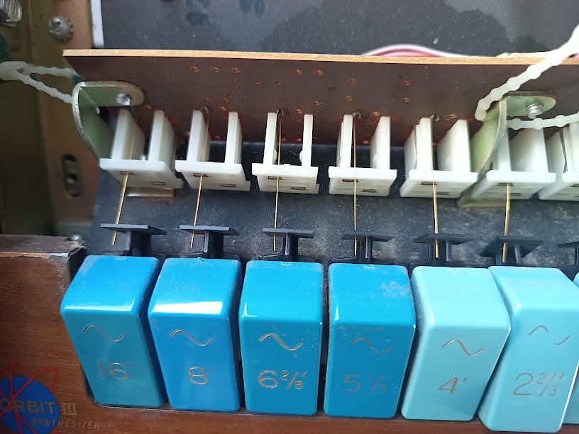 Upper manual stop tabs from behind. The white plastic plungers actuate fine gold contact wires against a bus bar when the tab is rocked forward. Foot-footage markings (16’, 8’, 6⅔’, 5⅓’, 4’, 2⅔’) are visible on the blue Tibias tabs; the “Orbit III Synthesizer” badge is at bottom left. Photo: Ryan Malloy.
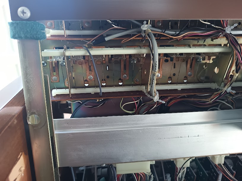 Underside of the stop tab switch mechanism. Copper contact bars (the bus that the stop tab wires touch) are visible through the mounting frame. This is the assembly described in patent US3317684. Photo: Ryan Malloy.
 -
Pivot the upper manual (Swell) forward
With the stoprail out of the way, the upper manual is accessible. It’s hinged at the rear on pivot pins. Lift the front edge and tilt the entire manual forward and down — it will rest against the stoprail or the lower manual front.
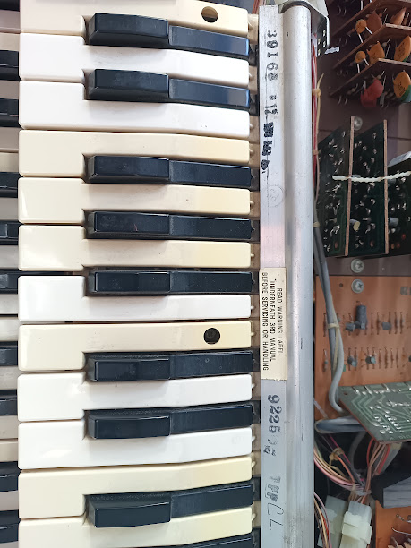 Upper manual tilted forward. The aluminum hinge rod runs the full width of the keyboard. A warning label on the underside of the key bed reads “READ WARNING LABEL UNDER MIDDLE KEYBOARD BEFORE HANDLING.” Photo: Ryan Malloy.
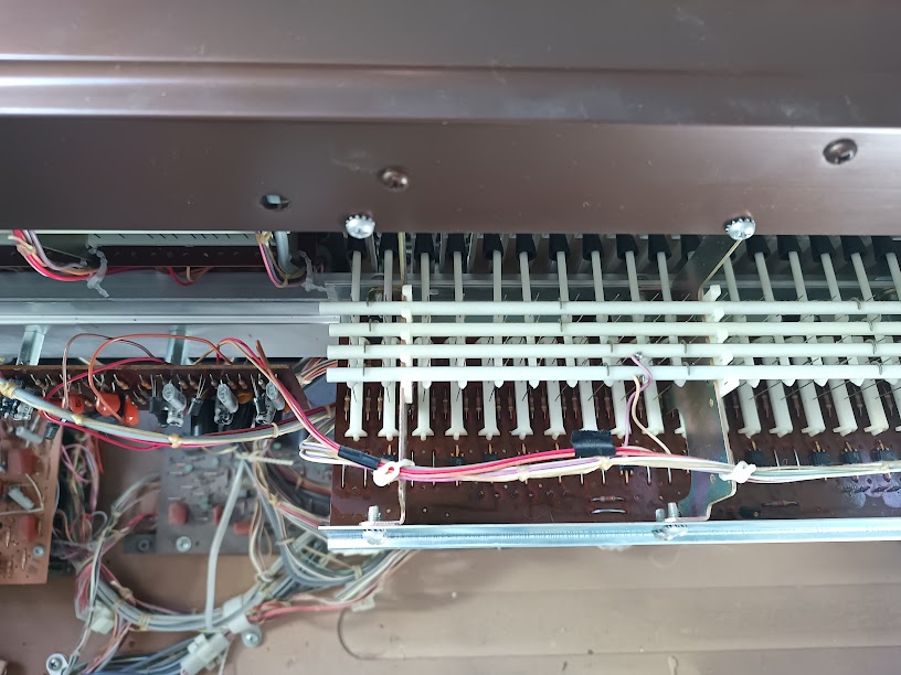 Key contact wire whiskers (upper manual, viewed from above). Each key’s wire makes contact with the bus bar when the key is depressed. These are the beryllium-copper + silver-platinum contacts described in patent US3330916. Photo: Ryan Malloy.
With the upper manual tilted forward, you can see the bus bars, contact wiring, and the main circuit boards behind the key bed.
-
Pivot the lower manual (Great) forward
Same procedure as the upper manual — hinged at the rear, lifts at the front edge, pivots forward. The same wire whisker caution applies. With both manuals pivoted, the full circuit board area is exposed.
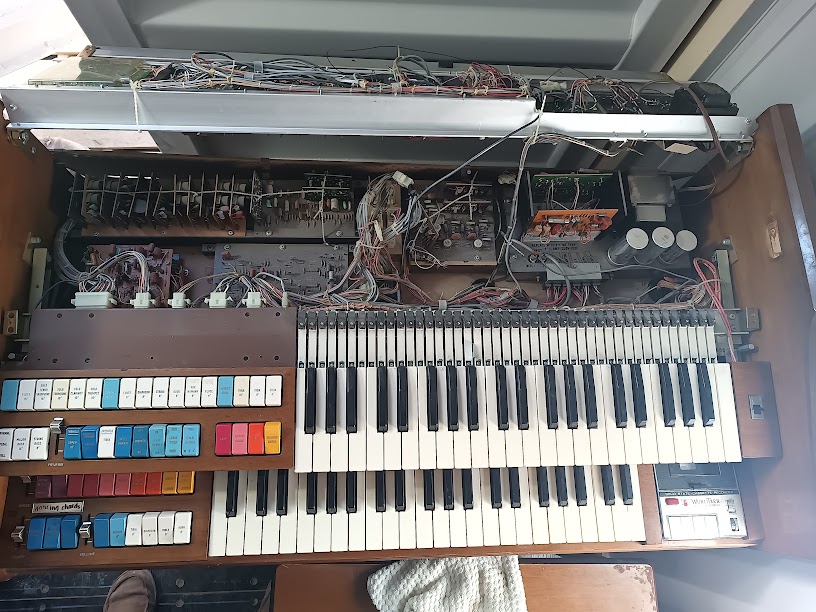
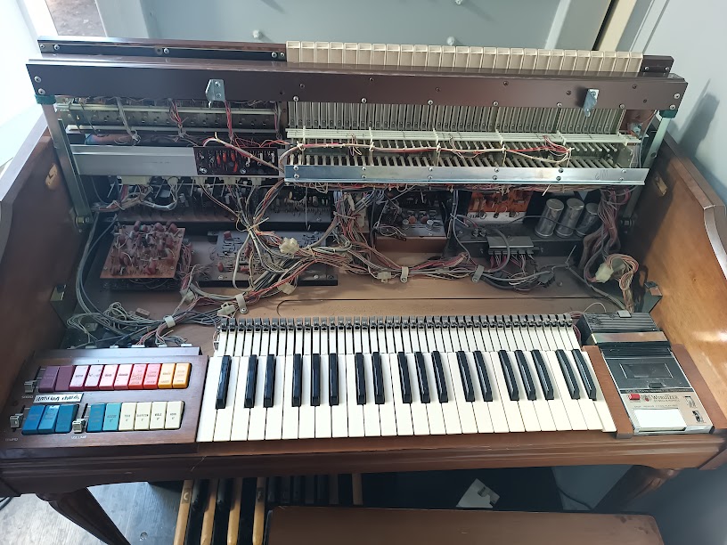 Console with upper manual removed and lower manual area exposed. Upper circuit boards and wiring harnesses visible across the top; large electrolytic capacitors (power supply) at upper right; the Orbit III section and cassette deck flank the lower keyboard. Photo: Ryan Malloy.
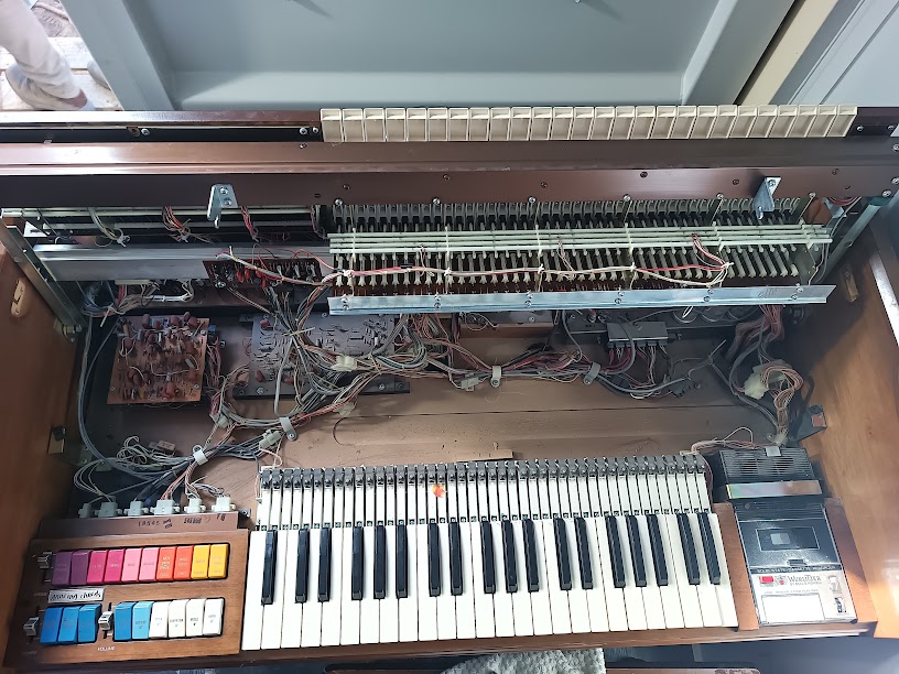 Overhead view with both keyboard areas open. Two rows of contact bus bars are visible at center. The dense wiring harness runs from the bus bars down to the circuit boards below. Photo: Ryan Malloy.
 -
Access the Orbit III
The Orbit III synthesizer panel sits below the lower manual. Once the lower manual is pivoted forward, the Orbit III’s circuit board and wiring are accessible from above. The Orbit III panel itself may also pivot or slide, depending on the specific production run — check for retaining screws or clips before forcing anything.
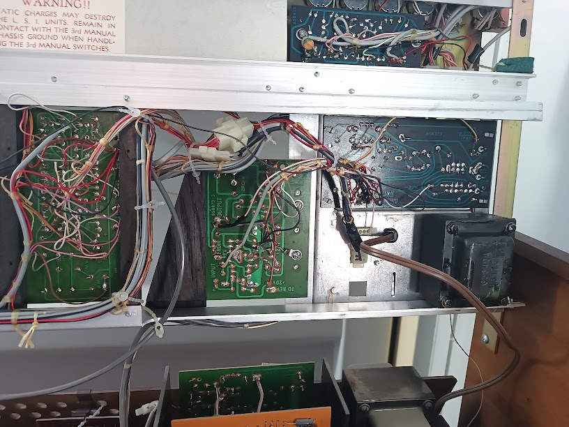
 Deepest view into the console cavity. Multiple PCB assemblies are visible: voicing boards (green, left), rhythm/percussion circuits (orange board, center-right), power supply electrolytics (large cans, right), and the dense point-to-point wiring that connects them. Photo: Ryan Malloy.
Factory ESD Warning
Section titled “Factory ESD Warning”A factory warning label is affixed to the chassis under the upper manual:
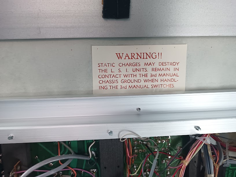 Factory ESD warning label. “3rd manual” refers to the Orbit III synthesizer. Photo: Ryan Malloy.
WARNING!! STATIC CHARGES MAY DESTROY THE L.S.I. UNITS. REMAIN IN CONTACT WITH THE 3rd MANUAL CHASSIS GROUND WHEN HANDLING THE 3rd MANUAL SWITCHES.
The “L.S.I. units” are the Large Scale Integration ICs — the divider-keyers and TOS chip. The “3rd manual” is the Orbit III (upper manual = 1st, lower manual = 2nd, Orbit III = 3rd). Wurlitzer’s instruction is to keep one hand on the metal chassis ground while touching any Orbit III switches or circuit board, to prevent static discharge through the ICs.
What’s Underneath
Section titled “What’s Underneath”With the top lid removed, the LSI board is immediately accessible at the top left of the console — the divider-keyers and TOS are right there without needing to tilt any keyboards. Deeper disassembly exposes the rest:
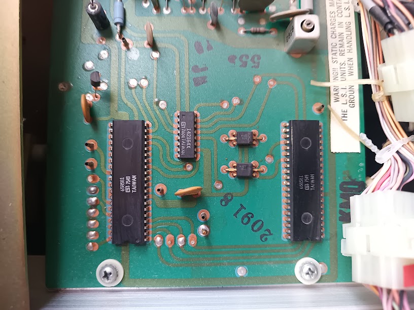 LSI board (PCB 20918), top left under the top cover. Two 40-pin divider-keyer ICs (Wurlitzer 658581, dated 7549) flank a smaller TOS IC (142164X, dated 7604). Two small ICs (AA 627) and 8–9 test points are also visible. The board-level ESD warning at upper right matches the factory label. Photo: Ryan Malloy.
- Bus bars — the horizontal metal rails that carry each note’s signal. One bus bar per note, running the width of the keyboard. The key contact wires touch these when a key is pressed.
- Contact wiring — the fine wire whiskers at the rear of each key. These are the signals that the shift register approach will read for the MIDI conversion.
- Divider-keyer ICs — Wurlitzer 658581 in 40-pin DIP packages. Two per manual, handling octave division and key gating. See IC Identification.
- TOS board — the Top Octave Synthesizer (142164X) that generates the master pitches for all organ voices.
- Voicing filter boards — the tone-shaping circuits that create flute, reed, and string voices from the raw square waves.
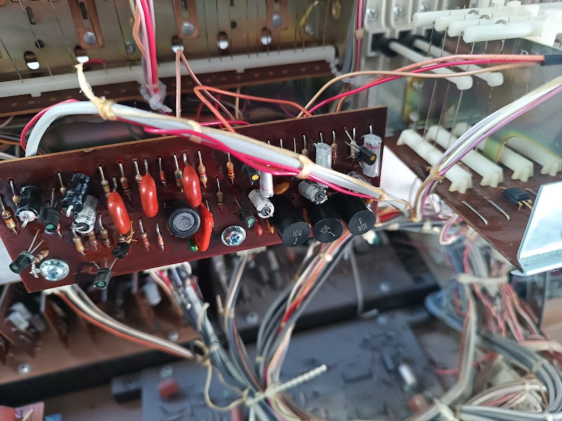 Voicing filter board (left side of lower keyboard area). Ceramic disc capacitors (red), electrolytic capacitors (black cylinders), and resistors form the filter networks that shape the raw square waves into flute, reed, and string voices. Photo: Ryan Malloy.
- Wiring harnesses — Wurlitzer house-made connectors (not AMP/Molex) connecting the keyboards to the main boards. Don’t disconnect these without labeling them first — they’re not keyed, and some are identical in size.
 Circuit boards behind the upper keyboard. Multiple PCB assemblies are mounted vertically on a metal chassis rail. The WARNING label about static charges is visible at top. A small transformer (right) serves the upper manual circuits. Photo: Ryan Malloy.
Reassembly
Section titled “Reassembly”Reverse order: Orbit III panel → lower manual → upper manual → stoprail → cheek blocks → top lid.
The manuals simply pivot back into their resting position — gravity and the hinge pins do the alignment. The stoprail pivots back up and clicks or latches into the cheek block mounts. The top lid slides back into its channel (rear edge first, then settle the front).
Check that all wire harnesses are clear of the hinge points before closing each layer. A pinched wire harness is the most common cause of “it worked before I opened it” problems — and can cause insulation damage that isn’t immediately obvious. See the caught wire incident above.
Service Manual Reference
Section titled “Service Manual Reference”The Wurlitzer service manual for the 555 documents this procedure with factory illustrations. If you’re doing regular maintenance, the service manual is worth acquiring — they surface on eBay periodically for $30–50. The community at Organ Forum is also an excellent resource for model-specific disassembly questions. Much of the procedure documented here was synthesized from Organ Forum threads covering 1970s Wurlitzer spinet and console organs.