Rhythm Section
Overview
Section titled “Overview”The 555 includes Wurlitzer’s Swingin’ Rhythm system — an analog pattern sequencer that first appeared as the standalone Model 5020 drum machine in 1969 and was subsequently built into Wurlitzer’s organ line through the 1970s. The 5020 was designed by Harold O. Schwartz, Peter E. Maher, and John E. Holt at Wurlitzer’s De Kalb Division.
The rhythm section on the 555 encompasses four related subsystems, all controlled from the left panel below the manuals:
| Subsystem | Function | Manual Page |
|---|---|---|
| Swingin’ Rhythm | Five preset rhythm patterns | 14 |
| Toy Counter | Additional percussion voices and fills | 14 |
| Dancing Chords | Auto-accompaniment — chords played in rhythm | 15 |
| Repeat | Attack percussion on organ keys | 13 |
Console Controls
Section titled “Console Controls”The features diagram from the owner’s manual shows the rhythm controls on the left side of the console:
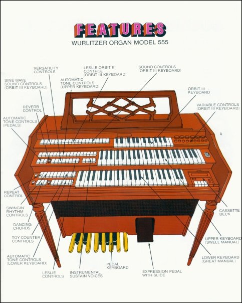 Console layout from the 1973 owner’s manual. The Swingin’ Rhythm Controls, Toy Counter Controls, Dancing Chords, and Repeat Control are all on the left panel below the upper manual. Image: The Wurlitzer Company.
Swingin’ Rhythm
Section titled “Swingin’ Rhythm”Available Patterns
Section titled “Available Patterns”Five preset rhythms, selected by pushbuttons:
| Pattern | Time Signature | Character |
|---|---|---|
| Waltz | 3/4 | Bass on 1, brush on 2 and 3 |
| Latin | 4/4 | Syncopated with block accents (bossa/cha-cha feel) |
| Swing | 4/4 | Shuffle feel with snare backbeat |
| Rock | 4/4 | Straight eighths, strong bass and snare |
| March | 4/4 | Military-style snare pattern |
A tempo control adjusts the master clock speed, and a tempo indicator light flashes on the beat.
Percussion Voices
Section titled “Percussion Voices”The Swingin’ Rhythm generates five analog percussion sounds, each with its own synthesis circuit:
| Voice | Synthesis Method | Character |
|---|---|---|
| Bass Drum | Low-frequency damped oscillator | Deep thud — a capacitor discharged through a tuned circuit produces a decaying sine wave |
| Snare | Filtered noise with envelope | Broad-spectrum burst shaped by a fast attack/decay envelope |
| Brush | Super-regenerative noise circuit | Softer, sustained noise — the “sizzle” sound |
| Block | High-frequency damped pulse | Sharp, clicky transient (woodblock/rimshot character) |
| Cymbal | Band-pass filtered noise with shimmer | Longer decay than snare, with amplitude modulation for metallic shimmer |
Architecture
Section titled “Architecture”The rhythm section follows the standard 1970s analog drum machine architecture: a clock oscillator drives a binary counter chain, and a diode matrix selects which counter states trigger which percussion voices. Each rhythm pattern is a different set of connections in the diode matrix — literally a hard-wired read-only memory.
graph TD
    CLK["Clock Oscillator<br/>(tempo-controlled RC)"] --> CNT["Binary Counter Chain<br/>(divides clock into beats)"]

    CNT --> DM["Diode Matrix<br/>(pattern ROM)"]

    DM -->|trigger| BD["Bass Drum<br/>Circuit"]
    DM -->|trigger| SN["Snare<br/>Circuit"]
    DM -->|trigger| BR["Brush<br/>Circuit"]
    DM -->|trigger| BL["Block<br/>Circuit"]
    DM -->|trigger| CY["Cymbal<br/>Circuit"]

    BD --> MIX[Rhythm Mixer]
    SN --> MIX
    BR --> MIX
    BL --> MIX
    CY --> MIX

    MIX --> VOL["Rhythm Volume"]
    VOL --> AMP["Main Amplifier Bus"]

    SEL["Pattern Select<br/>(Waltz · Latin · Swing · Rock · March)"] -.->|selects matrix row| DM

    style CLK fill:#92400e,color:#fef3c7,stroke:#d97706
    style DM fill:#78350f,color:#fef3c7,stroke:#d97706
    style AMP fill:#065f46,color:#d1fae5,stroke:#10b981
How the Diode Matrix Works
Section titled “How the Diode Matrix Works”The diode matrix is the heart of the pattern generator. It’s an elegant analog solution to the problem of storing repeating sequences — essentially a crossbar switch where each intersection is either connected (diode present) or not.
The binary counter cycles through a fixed number of states (typically 12 or 16 steps per measure). Each counter state represents a beat subdivision. At each state, the matrix determines which voices fire:
| Step | Bass | Snare | Brush | Block | Cymbal |
|---|---|---|---|---|---|
| 1 | x | x | |||
| 2 | x | ||||
| 3 | x | ||||
| 4 | x | ||||
| … |
Each “x” is a physical diode soldered on the pattern board. Changing the pattern means switching to a different set of diode connections — either a different section of the same board or a physically separate matrix, selected by the pattern pushbuttons.
Toy Counter
Section titled “Toy Counter”The Toy Counter is a secondary percussion circuit that adds fills and accent patterns on top of the main Swingin’ Rhythm. The name comes from its circuit topology — a counting circuit (binary counter) that sequences through additional trigger outputs, producing rhythmic subdivisions that complement the main pattern.
In theatre pipe organ tradition, the “toy counter” was the department of the organ that controlled physical percussion instruments (drums, cymbals, train whistles, bird calls). Wurlitzer borrowed the name for their electronic version — a counter circuit that plays toy-like percussion accents.
The Toy Counter has its own controls on the left panel and can be enabled or disabled independently of the main rhythm.
Dancing Chords
Section titled “Dancing Chords”Dancing Chords is an auto-accompaniment feature that ties chord voicing to the rhythm clock. When engaged, chords played on the lower manual (or detected from the pedals) are automatically gated in time with the rhythm pattern — the chord sustains, cuts, and re-attacks in a rhythmic pattern rather than sounding continuously.
This feature bridges the rhythm section and the organ’s tone generation — the rhythm clock gates the keying circuit, turning the sustained organ tone into a rhythmic pulse. It’s an early form of what later organ manufacturers would call “auto-chord” or “chord memory.”
Repeat (Attack Percussion)
Section titled “Repeat (Attack Percussion)”The Repeat control adds a re-triggering envelope to held organ notes. Instead of a note sustaining continuously when a key is held, the envelope repeatedly attacks and decays — creating a tremolo-like percussive effect synchronized to the rhythm clock.
This is distinct from the organ’s tremolo effect (which modulates pitch and amplitude with the LFO). Repeat is a rhythmic re-attack, creating the illusion of a guitarist or mandolinist re-picking a sustained chord.
Signal Path
Section titled “Signal Path”The rhythm section’s output is entirely separate from the organ voices until the final mixing stage:
graph LR
    RHY["Rhythm Voice<br/>Circuits"] --> RVOL["Rhythm Volume"]
    DC["Dancing Chords<br/>Gate"] --> KEY["Lower Manual<br/>Keying"]
    RPT["Repeat<br/>Clock"] --> ENV["Note Envelope<br/>Re-trigger"]

    RVOL --> MIX["Main<br/>Mixing Bus"]
    KEY --> MIX
    ENV --> MIX

    ORG["Organ Voices<br/>(Upper · Lower · Pedal)"] --> MIX
    ORB["Orbit III"] --> MIX

    MIX --> FX["Tremolo · Vibrato<br/>Reverb"]
    FX --> AMP["Amplifier"]
    AMP --> LSL["Leslie · Stationary<br/>Speakers"]

    style RHY fill:#92400e,color:#fef3c7,stroke:#d97706
    style ORG fill:#92400e,color:#fef3c7,stroke:#d97706
    style ORB fill:#92400e,color:#fef3c7,stroke:#d97706
    style AMP fill:#78350f,color:#fef3c7,stroke:#d97706
The rhythm voices, gated chords, and repeat envelopes all feed the same amplifier bus as the organ and Orbit III. The rhythm has its own volume control so the player can balance percussion against organ tone.
MIDI Conversion Relevance
Section titled “MIDI Conversion Relevance”The rhythm section presents two opportunities for the MIDI conversion project:
MIDI-In (controlling the rhythm from external sources):
- Pattern selection via relay-driven switching of the pattern pushbuttons — documented in the Output Inventory as a binary target (confidence: Low)
- External clock sync — if the rhythm clock accepts an external trigger, MIDI Clock messages could synchronize the Swingin’ Rhythm to a DAW or drum machine. This is an open investigation item
MIDI-Out (sending rhythm triggers externally):
- Tapping the diode matrix outputs could provide MIDI Note On triggers synchronized to each voice — turning the analog rhythm into a MIDI drum trigger
- The tempo clock itself could drive MIDI Clock output for synchronizing external gear
Current Status
Section titled “Current Status”The rhythm section has not yet been tested on this particular instrument. It’s listed on the initial assessment checklist along with individual tab stops, reverb, and the cassette deck.
Given the instrument’s age and storage history, common failure modes to watch for include:
- Dried electrolytic capacitors in the voice circuits (causes weak or missing percussion sounds)
- Corroded pattern select contacts (causes stuck or intermittent pattern switching)
- Clock oscillator drift (causes unsteady tempo)
The Swingin’ Rhythm circuit is entirely discrete analog — no proprietary ICs — so any failures should be repairable with standard components.