Leslie Control
The Leslie Unit — CBS / Electro Music
Section titled “The Leslie Unit — CBS / Electro Music”The 555’s Leslie is not a Wurlitzer product. The rear-panel service labels identify it as manufactured by Electro Music, C.B.S. Musical Instruments — a division of Columbia Broadcasting Systems, Inc., Pasadena, California 91109. This is the company that made Leslie speakers (CBS acquired the Leslie Speaker brand from Electro Music in 1965).
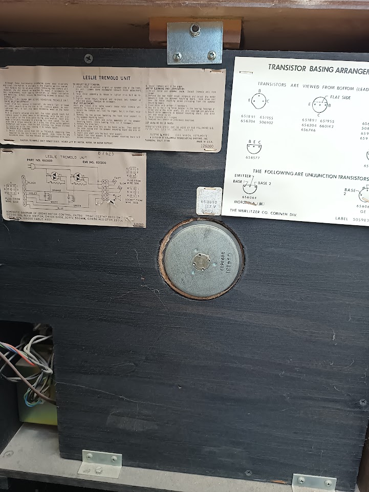 Leslie Tremolo Unit rear panel: service/maintenance label (top), schematic (bottom left), and motor assembly (center). Photo: Ryan Malloy.
Unit identification:
- Part No. 660890
- EMI No. 600900
- 117 VAC, 60 Hz, 18 Watts
- US Patents: 3,315,760 · 3,080,786 · 3,174,579
How the 555 Controls the Leslie Today
Section titled “How the 555 Controls the Leslie Today”The console has a three-position Leslie switch: Off / Slow / Fast. The slow (chorale) and fast (tremolo) speeds produce the characteristic Leslie sound — the spin-up and spin-down transitions between speeds are where most of the musical drama lives.
The schematic label on the rear panel documents the complete motor control circuit:
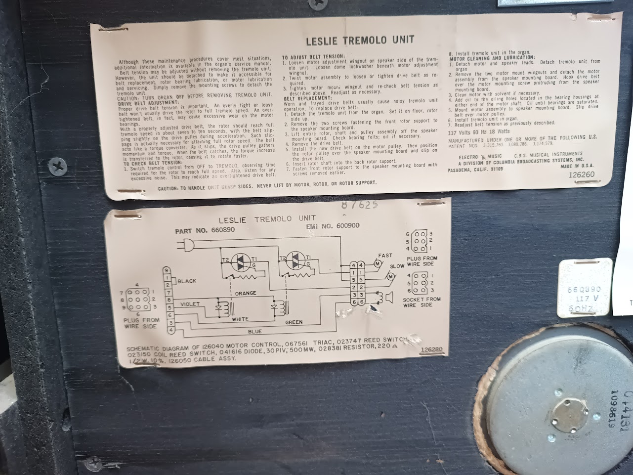 Leslie Tremolo Unit schematic (Part No. 660890, EMI No. 600900) and maintenance instructions. Handwritten “87625” may be a service or inventory number. Photo: Ryan Malloy.
Motor Control Circuit
Section titled “Motor Control Circuit”The Leslie uses a TRIAC-based electronic speed controller with reed switch speed selection — more sophisticated than the simple relay switching assumed in the original investigation plan.
| Component | Part No. | Function |
|---|---|---|
| Motor Control | 126040 | Main control board |
| TRIAC | 067561 | AC power switching element |
| Reed Switch | 023747 | Speed selection (magnetically actuated) |
| Coil Reed Switch | 023150 | Coil that actuates the reed switch |
| Diode | 041616 | 30 PIV, 500 mW — snubber/protection |
| Resistor | 028381 | 220 Ω, 1/2W, 10% |
| Cable Assembly | 126050 | Wiring harness |
Wiring
Section titled “Wiring”The schematic documents wire colors on both connectors:
| Wire Color | Connection |
|---|---|
| Black | Motor control circuit |
| Orange | Motor control circuit |
| Violet | Motor control circuit |
| White | Motor control circuit |
| Green | Speed select |
| Blue | Speed select |
Two connectors interface the Leslie to the organ: a plug (from the organ wiring harness) and a socket (on the Leslie unit). The socket side labels the connections as FAST and SLOW — confirming that the console switch selects between two speed states by energizing different reed switch coils, which in turn configure the TRIAC to drive the single AC motor at the appropriate speed.
What This Means for MIDI Control
Section titled “What This Means for MIDI Control”The TRIAC + reed switch architecture is actually easier to interface than direct motor winding switching:
- The reed switch coils are low-voltage, low-current control signals — the TRIAC handles the mains-voltage motor switching
- The console switch energizes a coil to actuate a reed switch, which configures the TRIAC circuit for slow or fast operation
- The MIDI interface needs to replicate this coil drive — a small relay or optocoupler in parallel with the console switch would work, leaving the original switch functional
Remaining Investigation
Section titled “Remaining Investigation”The schematic on the label resolves most of the unknowns from the original investigation plan. What remains:
-
Trace the console switch to the coil — with the organ unplugged, verify which wires from the Off/Slow/Fast switch connect to the reed switch coils. The schematic documents the circuit topology; this step confirms the physical routing.
-
Measure coil drive voltage and current — with the organ powered, measure the voltage across the reed switch coil in Slow and Fast positions. This determines the relay/optocoupler spec for the MIDI interface.
-
Verify connector pinout — match the physical connector pins to the schematic’s numbered pin assignments and wire colors.
Belt Maintenance
Section titled “Belt Maintenance”The service label also documents belt tension adjustment, belt replacement, and motor lubrication procedures. Key points:
- A properly adjusted drive belt should bring the rotor to full tremolo speed in about seven to ten seconds
- Worn or frayed belts usually cause noisy operation — replacement requires removing the tremolo unit from the organ (set it on the floor, rotor side up)
- Motor bearings should be oiled at the oiling holes at either end of the motor shaft until bearings are saturated
MIDI-to-Leslie Interface Options
Section titled “MIDI-to-Leslie Interface Options”Now that the Leslie’s TRIAC + reed switch control circuit has been identified, the interface design is straightforward:
Scenario A: Reed Switch Coil Drive Confirmed
The console switch energizes reed switch coils that configure the TRIAC for slow or fast motor speed. The MIDI interface replicates this coil drive in parallel with the original switch:
Interface: ESP32 GPIO → ULN2803 Darlington driver → small relay or optocoupler across reed switch coil
The ESP32 drives two channels that replicate the three-position console switch:
- Both off = Leslie off
- Channel 1 on = slow (chorale)
- Channel 2 on = fast (tremolo)
MIDI mapping: CC#80 (General Purpose 5) with three zones:
| CC#80 Value | Leslie State | Behavior |
|---|---|---|
| 0–42 | Off | Motor stops |
| 43–95 | Slow (chorale) | ~40 RPM |
| 96–127 | Fast (tremolo) | ~340 RPM |
This mirrors the CC#80 convention used by Hammond-Suzuki and several Leslie MIDI controllers.
Scenario B: Variable Voltage (DC Motor) Less Likely
If the Leslie uses a DC motor with voltage-controlled speed:
Interface: ESP32 DAC → op-amp gain stage → PWM motor driver (L298N or equivalent)
Continuous speed control becomes possible — the mod wheel could sweep the Leslie from stopped through chorale to tremolo speed in a continuous arc.
MIDI mapping: CC#1 (Mod Wheel) for continuous speed, 0–127 mapping to full RPM range.
This is less likely in a 1974 organ but would be the most musically expressive option.
Scenario C: ESP32 Micro-VFD Future Path
The ESP32-S3’s MCPWM peripheral can generate variable-frequency SPWM to drive the motor at any speed from ~10 Hz (60 RPM) to 60 Hz (360 RPM) through a full H-bridge, with about $10 of additional components (bridge rectifier, bulk cap, 4x MOSFETs, gate driver). Constant V/Hz scaling maintains motor flux across the entire speed range — the motor operates at optimal slip everywhere, unlike the TRIAC approach where low-speed operation means high slip and wasted energy.
This unlocks capabilities that Scenario A cannot provide:
- Continuous speed control via MIDI CC#1 (mod wheel)
- Programmable ramp-up and ramp-down profiles shaped in firmware
- Any speed between 60 and 340 RPM, not just two fixed presets
See Leslie Motor Simulations for SPICE simulation data comparing VFD and TRIAC motor drive — including waveform plots, power analysis, and the candidate BOM.
Status: Simulated and confirmed viable for this motor. Build after Scenario A is proven.
MIDI Mapping Recommendation
Section titled “MIDI Mapping Recommendation”Regardless of motor type, the recommended MIDI mapping provides two complementary controls:
| MIDI Message | Function | Use Case |
|---|---|---|
| CC#80 | Leslie speed preset (Off/Slow/Fast) | Foot switch, sequencer automation |
| CC#1 (Mod Wheel) | Continuous speed (if Scenario B) | Expressive real-time control |
CC#80 is the primary control — it works with the simplest relay interface and matches existing Leslie MIDI conventions. CC#1 is reserved for continuous control if the motor type supports it.
Prior Art
Section titled “Prior Art”The Leslie has been MIDI-controlled since the late 1980s. These existing solutions inform both the MIDI mapping and the electrical interface:
- Hammond-Suzuki Leslie 2101mk2 — purpose-built MIDI Leslie with built-in MIDI input. Uses CC#80 for speed selection, exactly as proposed above. The industry standard reference.
- Neo Instruments Ventilator — Leslie simulator pedal with MIDI input. Demonstrates the CC#80 slow/fast convention and adds CC#1 for continuous rotation speed in its “advanced” mode.
- Voce V5+ Organ Module — MIDI-to-Leslie interface that drives real Leslie speakers from MIDI. Relay-based speed switching, confirming Scenario A is the standard approach for real motors.
- Motion Sound Pro-3T — rotary speaker with MIDI speed control, using a DC motor and continuous speed adjustment via MIDI CC.
The consensus across these products: CC#80 for three-state switching (off/slow/fast) is the de facto standard. Our implementation follows this convention for maximum compatibility with existing MIDI controllers and DAW setups.
Cross-References
Section titled “Cross-References”- Leslie Motor Simulations — TRIAC vs VFD simulation comparison
- Simulations — CapSense detection chain simulations
- Approach — overall MIDI conversion architecture
- Implementation Roadmap — build sequence and phase plan