Expression Pedal
Overview
Section titled “Overview”The expression pedal on the 555 is a two-axis controller — an unusual design for a consumer organ of this era. Most home organs offered only a single-axis volume swell (toe-heel). The 555 adds a lateral push-left axis that routes to the Orbit III synthesizer’s Slide circuit, giving the player real-time pitch bend from the same pedal.
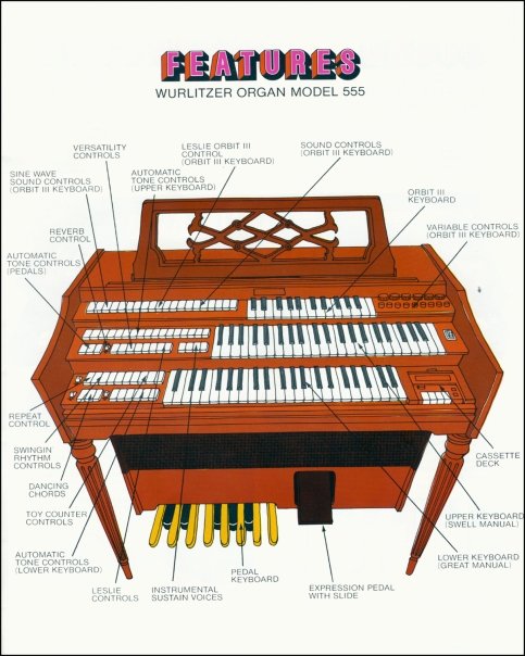 Console layout from the 1973 owner’s manual. The expression pedal sits below the pedalboard at the player’s right foot position. Image: The Wurlitzer Company.
Vertical Axis — Volume Swell
Section titled “Vertical Axis — Volume Swell”The primary axis. Rocking the pedal toe-down increases volume; heel-down decreases it. A potentiometer mechanically linked to the rocker shaft controls the main amplifier gain. This is the same “swell shoe” mechanism that pipe organists have used since Abraham Jordan first fitted shutters to a swell box in 1712 — but instead of opening and closing physical shutters over organ pipes, the electronic version adjusts an amplifier’s gain.
The potentiometer is almost certainly a logarithmic (audio) taper — the resistance changes slowly at low volume and rapidly at high volume, compensating for the logarithmic response of human hearing. A linear taper pot in a volume application would make most of the audible range crowd into the first 20% of pedal travel, with the remaining 80% producing barely perceptible change.
The volume swell affects the entire instrument — both manuals, pedalboard, Orbit III, and rhythm section all pass through the expression-controlled amplifier stage. It sits at the very end of the signal architecture chain, just before the speakers.
Lateral Axis — Pitch Slide
Section titled “Lateral Axis — Pitch Slide”The secondary axis. Pushing the pedal to the left (with the side of the right foot) engages a second potentiometer or switch that routes to the Orbit III’s Slide circuit on the Switching and Special Effects (S&SE) board. This bends the VCO pitch downward — typically about a semitone, enough for blues-style note bending, trombone slides, or vibrato effects too slow for the LFO to produce convincingly.
The lateral mechanism is spring-loaded to return to center when released. This is functionally identical to a pitch wheel on a modern synthesizer, but operated by foot rather than hand — a design choice that keeps both hands free for playing the three keyboards.
Heritage
Section titled “Heritage”The expression pedal’s dual-axis design didn’t appear from nowhere — it descends from a lineage of foot-operated pitch controllers in home organs.
Lowrey Glide (1956): Lowrey introduced the first foot-operated pitch bend in consumer organs — a kick switch on the side of the expression pedal that dropped the organ pitch by approximately one semitone. Lowrey marketed it for “the effects of a Hawaiian guitar glide, the smear of a trombone, the glissando of singing strings.” The Glide was a momentary switch (on/off), not a continuous controller.
Wurlitzer Pedal Glide (1960s–70s): Wurlitzer’s implementation evolved the concept from a binary switch to a continuous controller — the lateral slide mechanism on the 555 provides variable pitch bend, not just a fixed semitone drop. This maps naturally to the Orbit III’s voltage-controlled architecture, where more lateral pressure produces more voltage change and therefore more pitch deviation.
The same pitch-bend-by-foot concept appeared across organ manufacturers throughout this period. Lowrey, Wurlitzer, and Hammond all shipped models with some form of pedal-operated pitch control, each adapting the idea to their own voice architecture.
Signal Routing
Section titled “Signal Routing”The two axes feed completely independent circuits. The volume axis controls the main amplifier; the lateral axis drives the Orbit III’s VCO. They share a pedal housing but share no electrical path.
graph TD
    EP["Expression Pedal<br/>(two-axis)"]

    EP -->|"vertical axis<br/>(toe-heel)"| VPOT["Volume Potentiometer<br/>(logarithmic taper)"]
    EP -->|"lateral axis<br/>(push-left)"| SPOT["Slide Potentiometer<br/>(linear taper)"]

    VPOT --> AMP["Main Amplifier<br/>Gain Control"]
    AMP --> SPK["Leslie · Stationary<br/>Speakers"]

    SPOT --> SLIDE["Orbit III<br/>Slide Circuit<br/>(S&SE Board)"]
    SLIDE --> VCO["Orbit III<br/>VCO Pitch"]

    UM["Upper Manual"] --> MIX["Mixing Bus"]
    LM["Lower Manual"] --> MIX
    PED["Pedalboard"] --> MIX
    ORB["Orbit III"] --> MIX
    RHY["Rhythm Section"] --> MIX

    MIX --> AMP

    style EP fill:#065f46,color:#d1fae5,stroke:#10b981
    style AMP fill:#78350f,color:#fef3c7,stroke:#d97706
    style VCO fill:#92400e,color:#fef3c7,stroke:#d97706
    style SPK fill:#78350f,color:#fef3c7,stroke:#d97706
The volume potentiometer sits in the signal path after the mixing bus — it attenuates the combined output of all four sound sources. The slide potentiometer feeds into the Orbit III before the mixing bus — it modifies the VCO pitch at the source.
Physical Design
Section titled “Physical Design”The pedal mechanism uses a balanced rocker assembly — a hinged platform that pivots on a shaft at the heel end. “Balanced” means the pedal stays wherever the player leaves it, without the player needing to hold it in position. This balanced swell pedal design was developed in the late nineteenth century for pipe organs and adopted universally by electronic organ manufacturers.
The vertical pivot (volume) uses the heel shaft. The lateral slide (pitch) uses a secondary mechanism at the toe end — likely a sliding plate or cam that moves perpendicular to the rocker’s primary axis, engaging the second potentiometer. The spring return on the lateral axis is essential — without it, the pitch would stay wherever the player left it, and every note played on the Orbit III would be out of tune until the pedal was physically re-centered.
Potentiometer Specifications (TBD)
Section titled “Potentiometer Specifications (TBD)”The exact pot specifications require bench measurement, but the likely values based on era-typical Wurlitzer practice:
| Parameter | Volume Pot (vertical) | Slide Pot (lateral) |
|---|---|---|
| Taper | Logarithmic (audio) | Linear |
| Resistance | 50 kΩ–100 kΩ (typical) | TBD |
| Travel | ~60° rotation | ~15 mm lateral |
| Wiring | Voltage divider to amplifier gain input | Voltage divider to S&SE board Slide input |
MIDI Conversion
Section titled “MIDI Conversion”The expression pedal contributes 2 analog inputs to the MIDI conversion — one per axis. These are the only analog inputs in the entire 153-input scan matrix (all key contacts are digital).
Input Side (MIDI-Out)
Section titled “Input Side (MIDI-Out)”| Axis | ESP32 Interface | MIDI Message | Resolution |
|---|---|---|---|
| Volume (vertical) | ADC channel | CC#11 (Expression) | 7-bit (128 steps) |
| Slide (lateral) | ADC channel | Pitch Bend | 14-bit (16,384 steps) |
The ESP32-S3’s built-in 12-bit ADC reads each potentiometer’s voltage directly. For CC#11, the 12-bit ADC reading (0–4095) maps to 7-bit MIDI (0–127) — more than enough resolution. For Pitch Bend, the 12-bit reading maps to 14-bit MIDI Pitch Bend (0–16383) — the extra resolution prevents the “zipper” effect (audible stepping) during smooth pitch slides.
Output Side (MIDI-In)
Section titled “Output Side (MIDI-In)”Both axes are also Output Inventory targets — external MIDI sources can drive the expression circuits:
| Axis | ESP32 Interface | MIDI Message | Mechanism |
|---|---|---|---|
| Volume (vertical) | DAC → op-amp | CC#11 (Expression) | Voltage injected at amplifier gain node |
| Slide (lateral) | DAC → op-amp | Pitch Bend | Voltage injected at S&SE Slide input |
The output stage uses MCP4728 DAC channels scaled through op-amp gain stages to match the organ’s voltage range. The volume axis is rated High confidence — it’s a straightforward potentiometer parallel. The slide axis is Medium confidence — the S&SE board’s Slide input voltage range needs bench verification before committing to a gain stage design.
ADC Considerations
Section titled “ADC Considerations”Potentiometers are inherently noisy — the wiper contact bounces across the resistive element, and carbon composition pots develop dead spots and noise with age. The ESP32 firmware needs:
- Oversampling and averaging — multiple ADC readings averaged together to smooth noise
- Dead zone at both ends — a small range at each extreme where the output clips to minimum/maximum, so a slightly dirty pot doesn’t cause the value to flutter at the endpoints
- Hysteresis — the MIDI value only changes when the ADC reading moves by more than a threshold in one direction, preventing jitter from generating a stream of redundant MIDI messages
These are standard techniques for any potentiometer-to-MIDI conversion. The bench probing plan Session 3 and Session 4 measurements will quantify the noise floor and linearity of each pot, informing the firmware filter constants.
Current Status
Section titled “Current Status”From the initial assessment:
| Axis | Status | Notes |
|---|---|---|
| Volume (vertical) | Working | Responds correctly during initial power-on test |
| Slide (lateral) | Present | Lateral push-left mechanism is physically intact — needs further testing with Orbit III engaged |
The lateral axis has not been fully tested because it requires the Orbit III synthesizer to be playing (the slide only affects the VCO pitch, so there’s nothing to hear without the Orbit III active). The bench probing plan includes oscilloscope measurement of the slide pot’s voltage output across its full travel range, and NanoVNA characterization of the pot’s resistance and impedance profile.
Investigation Queue
Section titled “Investigation Queue”These unknowns feed into the Output Inventory investigation queue and must be resolved at the bench:
- Measure volume pot — resistance value, taper (log vs. linear), voltage range at amplifier gain input
- Measure slide pot — resistance value, taper, voltage range at S&SE Slide input
- Test lateral axis with Orbit III playing — confirm pitch bend range, direction, and spring return behavior
- Characterize pot noise — ADC readings while slowly sweeping each axis, looking for dead spots, scratchy regions, and noise floor
- Determine pot replacement compatibility — if cleaning doesn’t resolve noise, what physical form factor and resistance value fits the pedal housing?